 |
| November 05, 2013 | Volume 09 Issue 41 |
Designfax weekly eMagazine

Archives
Partners
Manufacturing Center
Product Spotlight
Modern Applications News
Metalworking Ideas For
Today's Job Shops
Tooling and Production
Strategies for large
metalworking plants
Aerospace machine tools and assembly systems:
Joint strike fighter requires new technology to make pieces fit
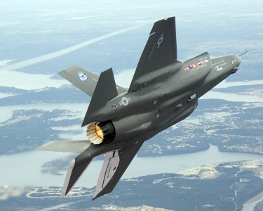
The F-35 Joint Strike Fighter, a multi-purpose military aircraft used by different branches of the U.S. military.
When you decide to build an aircraft piece by piece, in different places, on different machine tools and assembly systems, then ship all those pieces to another location for final production, challenges abound. In the case of the F-35, the Joint Strike Fighter designed to replace the F-16, A-10, and Harrier jets, among others, these production challenges have stimulated a truly international partnership of innovative thinking. The result has been a machine tool control scenario that indeed "pushes the envelope" for CNC design, engineering, and application technology.
Lockheed Martin leads the JSF (Joint Strike Fighter) team, which comprises itself and partners Northrup Grumman, BAE Systems (UK), Pratt & Whitney, and GE, each of whom has specific components and/or structures to produce for the final assembly. That final assembly and the estimated 5,000 units to follow will be produced at Lockheed Martin's main facility in Fort Worth, Texas. These component/structure suppliers, their sub-contractors, and their machine tool/assembly system suppliers, however, literally span the globe, from the U.S. to the UK, Spain, Germany, Japan, Italy, and elsewhere.
What would initially seem a Tower of Babel revisited has, on the contrary, become a monument to the cooperation and fiscal responsibility that emerges from a true joint venture. Working from the approved F-35 designs of Lockheed Martin, who won the contract over Boeing's designs in October 2001, all JSF team members have cooperated in the build-up of machinery and systems unique in the world.
Lockheed Martin in Ft. Worth has acquired a structures machinery center (5-axis) and flexible overhead gantry (FOG) milling machine from DST in Germany, as well as five giant U.S.-made wing-drilling machines. Meanwhile, its sister plant in Palmdale, Calif., has acquired one DST machine. Northrup Grumman purchased five ADS (applied drilling systems) from Spanish machine tool builder MTorres, Disenos Industriales, for use at its Palmdale, Calif., plant, as well as one DST machine for its El Segundo, Calif., plant to manufacture and assemble its portion of the F-35 fuselage. BAE Systems in the UK also acquired two DST machines for its work with British Aerospace.
These machine tools and assembly systems, seemingly disparate in nature and definitely international in origin, share common control technology developed by Siemens into the aerospace version of its SINUMERIK 840D CNC and compatible SIMODRIVE 611D motor and drives packages.
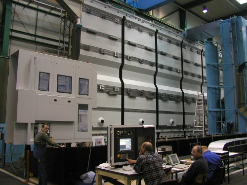
Siemens 840D CNC used to control all axes on huge gantry mill; includes TRAORI (transformation orientation), where the relative position of the tool tip to the workpiece is factored for greater precision in machining.
Unique among the features of this control package are the ability to have the control calculate the complex 5-axis transformations in real time versus relying on an upstream post processor (PP). Using this capability in conjunction with advanced probing routines eliminates the need for time-consuming finite part alignment, resulting in a substantial reduction in part set-up time. This advancement is achieved by the use of the onboard TRAORI transformation orientation, a high-level language for kinematic machine transformation, as well as the Virtual NC Kernel package (VNCK), a verification software that prevents any deviation in machining from the simulation modeling.

The conventional manner to generate the CNC cutter path requires CAD/CAM data be passed through a post processor to convert the data into usable information for the CNC. The CAD/CAM data defines the tool path in the workpiece coordinate system, tooling lengths, diameters, and tool inclination required to cut the part. The PP uses this information to calculate point-to-point machine axis movements required to cut along the workpiece contour in machine coordinates. This means huge data volume of single-axis movements for the cartesian and orientation axis are transferred to the CNC and updated with each interpolation cycle time. This method has been used since the early days of 5-axis machining because machine controls lacked the power and sophistication to transform this kinematic transformation in real time. The biggest drawback to this method is that the tool path data and tooling information are lost during the conversion of the data for use in the CNC. Thus, accurate compensation for part misalignment or tooling changes is not possible.
With TRAORI, all the programming is related to the TCP (tool center point) moving along the defined workpiece contour. According to the machine kinematic and tool length, the TCP is referenced to the machine pivot point within the work envelope, whether by laser beam or interpolated visual image. While changing the tool orientation, contour violation is avoided, as TRAORI enables compensation movements of the involved cartesian axis. Furthermore, far less data needs to be transferred from the upstream PP, due to the fact that the tool orientation is described by means of a start and end vector of your programmed tool path and all intermediate points are calculated within the CNC controller. By embracing this programming method, the CNC file represents a sort of neutral format, hence the same part program can be executed on different machine tool kinematics. Even better, there is no longer the necessity that the PP needs to consider manufacturing tolerances down to tiny misalignments of the rotary axis, since that is all getting compensated by the internal 840D machine transformation.
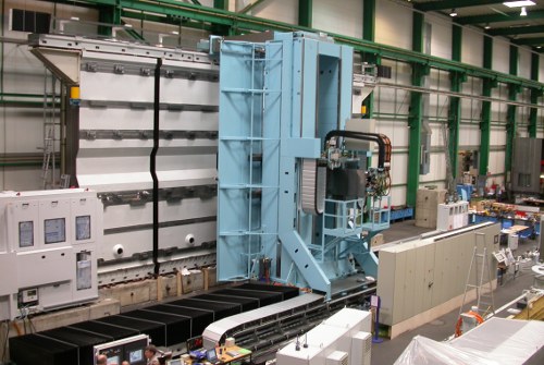
Ingersoll vertical gantry mill used to prep the wing sections of the Joint Strike Fighter at Lockheed.
On the MTorres drilling stations, the cutting head has a built-in enclosure vision system, comprising camera, light, optics, software for image processing, and even a positive pressure similar to a cleanroom concept to keep out penetrating dust and chips.
Thus, a single block transformation in real time can be made to compensate for various factors, including tool length, thermal expansion of machine components, different kinematics between similar machines, and more.
Likewise, the VNCK software instantly compares actual cutting conditions and axes movements to the simulation model, in this case, CATIA V Non-Uniform Rational B-Splines (NURBS), Macros, Cycles, 5-Axis Transformation, individual machine data, Frames, and high-level language commands precisely.
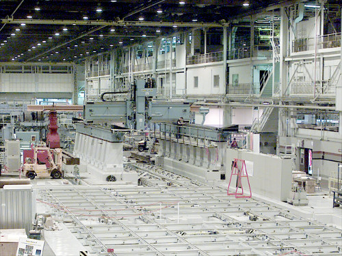
Droop + Rein gantry mill.
In the Frames mode, TRAORI enables full rotate, translate, mirror, and scale capability in the plane of the worktable rather than merely the programming. This is especially critical on the thin wall, floor, and incline cuts required in aerospace aluminum and titanium structures and skins.
Once machined, the linear and rotary alignment of the wing substructure would normally be programmed offline, but this is unnecessary on the JSF project, owing further to the onboard control enhancements. By putting the post-processor function inside the NC, Siemens engineers eliminated the need to repost the program for each machine. The alignment is optimized even for variances in volumetric air pressure in the different cities where machining is done.
As an example of how TRAORI is helping these JSF contractors, MTorres engineer Martin Flores ran a process study for the construction of the machines his company produced for Northrup Grumman.
The TORRESDRILL F35 ADS (applied drilling systems) are self-contained, 6-axis CNC machines used for fastener hole drilling in structures comprising composite skins and webs with aluminum and titanium frames and longerons. Hole sizes range from 3/16 in. to 3/8 in. diameters with material stack thicknesses to 3/4 in.
Three of the five in-line ADS perform drilling and countersinking, while the other two are set up on common X-axis beams to support two work zones, for use in tandem on the same component or independently, as production mandates. When working in tandem, the two machines drill/countersink approximately 4,500 holes total on a single structure.
After the optimum spindle was determined for the toughest requirement (3/8-in. holes in titanium), an FEA (Finite Element Analysis) was conducted to determine structural rigidity of the machine and drives, using acceleration/and overall speed objective criteria. The study included dynamic effect (natural frequency) and its impact on dynamic performance (gain in positioning loop, maximum jerk, etc.)
The study concluded with critical information on the ADS performance and conformance to specification, before fabrication began, such as:
- Deflection under the tool tip under theoretical loads in the worst-case position;
- Calculation of the structural rigidity in the three Cartesian directions;
- Calculation of machine modes and frequencies;
- Tool tip deflection due to inertial loads;
- Dynamic performance; and
- Mechatronic performance.
Another critical element was countersinking to required accuracy. All external fasteners on the JSF need to meet critical surface flushness, and any deviation would result in huge defect losses for the contractor.
By inclusion of a pressure foot on the spindle assembly with a position-monitoring device, the system simultaneously stabilizes the part during drilling to eliminate vibration. Actual position of the part is also fed to the control, which executes the cutting program on this basis, rather than a predetermined sequence and orientation.
Thus, the controller (Siemens 840D with TRAORI) can correct for any part movement within the work envelope to ensure the optimum efficiency of the operations.
Likewise, the length and diameter of the cutting tools are continuously monitored, again assuring accurate positioning and creating a tool-wear monitoring system for controller reference. A digital torque-monitoring device transmits actual drilling torque values from the machine controller. Breakage or excess wear automatically trigger an alarm, an escape route from the drilling point to the tool changer, replacement, and repositioning with the new tool characteristics reoriented to the actual drill point in real time.
As referenced earlier, this tool system works with an onboard vision system that measures reference points in the assembly jig. It then transfers data to the controller, which performs the translation of the part program to the actual position of the workpiece.
On screen, the HMI allows an operator to access all the following, for all five ADS in the assembly line:
- CNC status;
- Conveyor status/control;
- Program control;
- Restart selection;
- Process parameter configuration;
- Tool management;
- Hole number in execution and overall drilled hole information in graphic format;
- Measurement data display from vision system or part probe;
- Running operations data;
- Diagnostic message window, event and alarm log file used by analysis software to determine set-up time, machine uptime, stops etc.
On a typical milling operation, the same dimension-critical tolerances apply, and again the TRAORI transformation orientation of the machine controllers factors greatly in the achievement of these goals.
All JSF variants have common outer mold lines with common structural geometries. This high degree of commonality results in significant cost savings for the various armed services, which will each utilize modified versions of the JSF. There are nine versions total planned.
BONUS VIDEO: Lockheed F-35 program production floor where machined composite parts are assembled.
BONUS VIDEO: A time lapse video of the F-35 Center Wing Assembly production line in Marietta, Ga. The high-tech production line uses orange Automated Guided Vehicles to move assemblies throughout the factory. The center wing assembly is the backbone of the F-35 -- wings and fuselages are attached at the final assembly facility in Fort Worth, Texas.
As with most of today's aerospace applications, wall thickness, stepover smoothness, pocket dimensions, and floor configurations continue to challenge machining center builders. Typical metal removal is > 90 percent, in most cases, plus the complex workpieces have webs with extremely thin-wall (often unsupported) and thin-pocket bottoms.
Through TRAORI transformation orientation, the actual position of the workpiece determines the cutting sequence. Plus, with the introduction of COMPCAD, a Siemens aerospace application-specific software, the machine control's compressor function is optimized and NURBS are taken to an even higher level of smooth contouring and surface chatter elimination.
Through an advanced look-ahead function, as well, the controllers onboard the majority of JSF project milling machines have the ability to round off block transformations using splines as a function of an axis-specific tolerance window. This avoids contour violations, increases the efficiency of acceleration/deceleration curves, and, most importantly, eliminates slow down/speed up at block transitions. Finally, through proprietary jerk limitation, optimized acceleration patterns ensure long-term avoidance of stress on mechanical components, also minimizing surface irregularities -- an absolutely critical factor in aerospace.
The following individuals contributed to this story: Dave Champa and Martin Flores, MTorres; John Killian, Lockheed Martin; Tom Crump, Northrop Grumman; and Nigel Rogers and Tim Shafer, Siemens.
For more information, contact: Siemens Energy & Automations, Machine tool business unit at www.SiemensCNC.com or email SiemensMTBUMarCom@sea.siemens.com.
Source: Siemens
Published November 2013
Rate this article
View our terms of use and privacy policy